
Hardware
DiPowerEdge DPE100
An open EMS that runs on site
Device integration, computation and real-time policy execution all happen on site, running independently of any cloud platform. It can also serve as a data-collection terminal for a cloud platform, enabled by your policy.
What it is
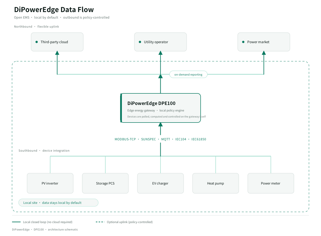
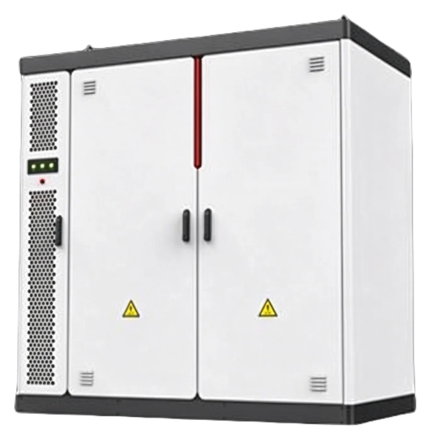
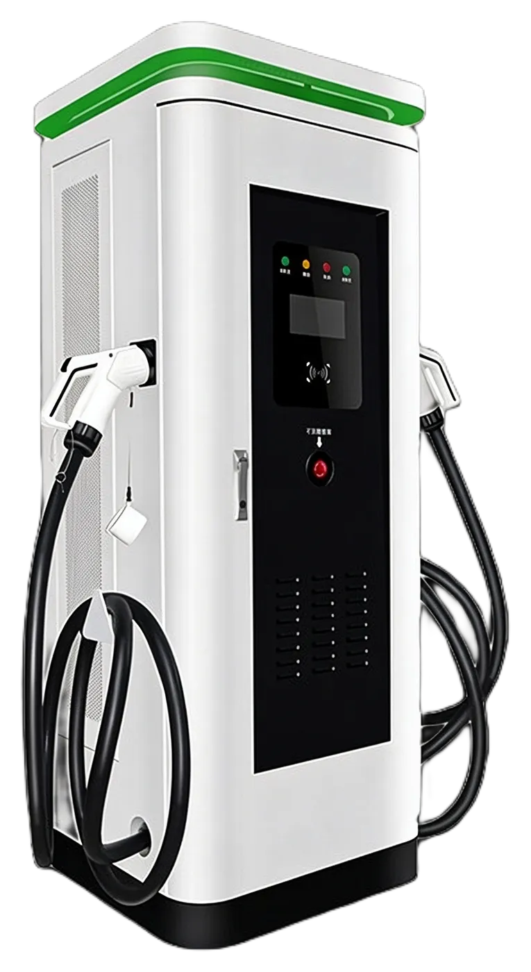
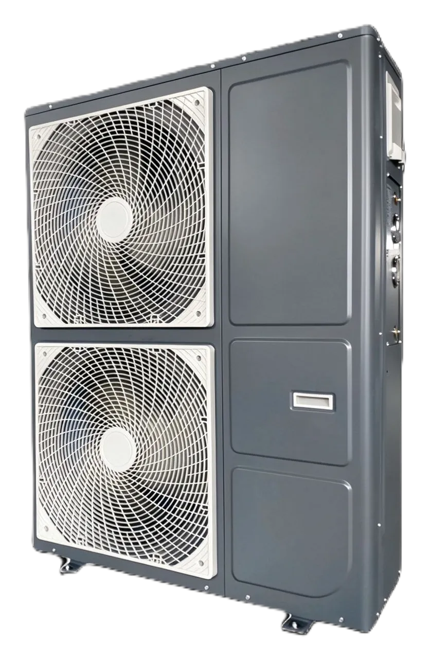
DPE100 is an edge energy gateway installed at the distribution site. Southbound it connects PV inverters, storage, EV chargers, heat pumps and meters. Northbound it reaches third-party clouds, utility operators and power markets, according to your policy.
It replaces the industrial PC that has been running in the cabinet for years. It is smaller, cooler and more reliable, and it takes the operating system off the site entirely.
Core capabilities
-
An open EMS
Any brand of device connects: each model arrives as its own device access package (DAP), each cloud as its own cloud access package (CAP), and the EMS strategy is yours to define. A device pack you develop yourself can be submitted for inclusion in the public release.
-
AI smart scheduling
Schedules are generated from time-of-use windows, tariffs and load, with manual configuration a click away.
-
Power markets and VPPs
Prepared for FCR / mFCR ancillary services, with plugin-based aggregator interfaces.
-
Commissioned in about five minutes
Power up, join the network, add devices.
-
AI-assisted device onboarding
A new device model goes from protocol document to working integration in roughly an hour.
-
Local web configuration
Commission and troubleshoot from a browser on site, with no proprietary software required.
-
EMS operating modes
Five modes: AI-EMS, Self Consume, Peak Shaving, Feed-in Priority and time-of-use. Each period takes its own mode and its own parameters.
-
System functions
Feed-in limiting caps exported power, import-power limiting caps the peak drawn from the grid, PV-curtailment avoidance reduces wasted yield, and closed-loop power-factor control holds the power factor at the point of connection within a set range.

Figures you can check
- Commissioning time
- 5 min Power up, join the network, add devices
- Onboarding a new device model
- 1 h From protocol document to a working integration
- Operating temperature
- −20 to +70 ℃ Continuous operation inside a distribution cabinet
- Serial ports
- 4 4 × RS-485 in the target specification
Each figure below is already stated elsewhere on this site, or comes straight from the hardware specification. We do not quote installation counts, customer numbers, or any other scale figure we cannot substantiate.
Interfaces
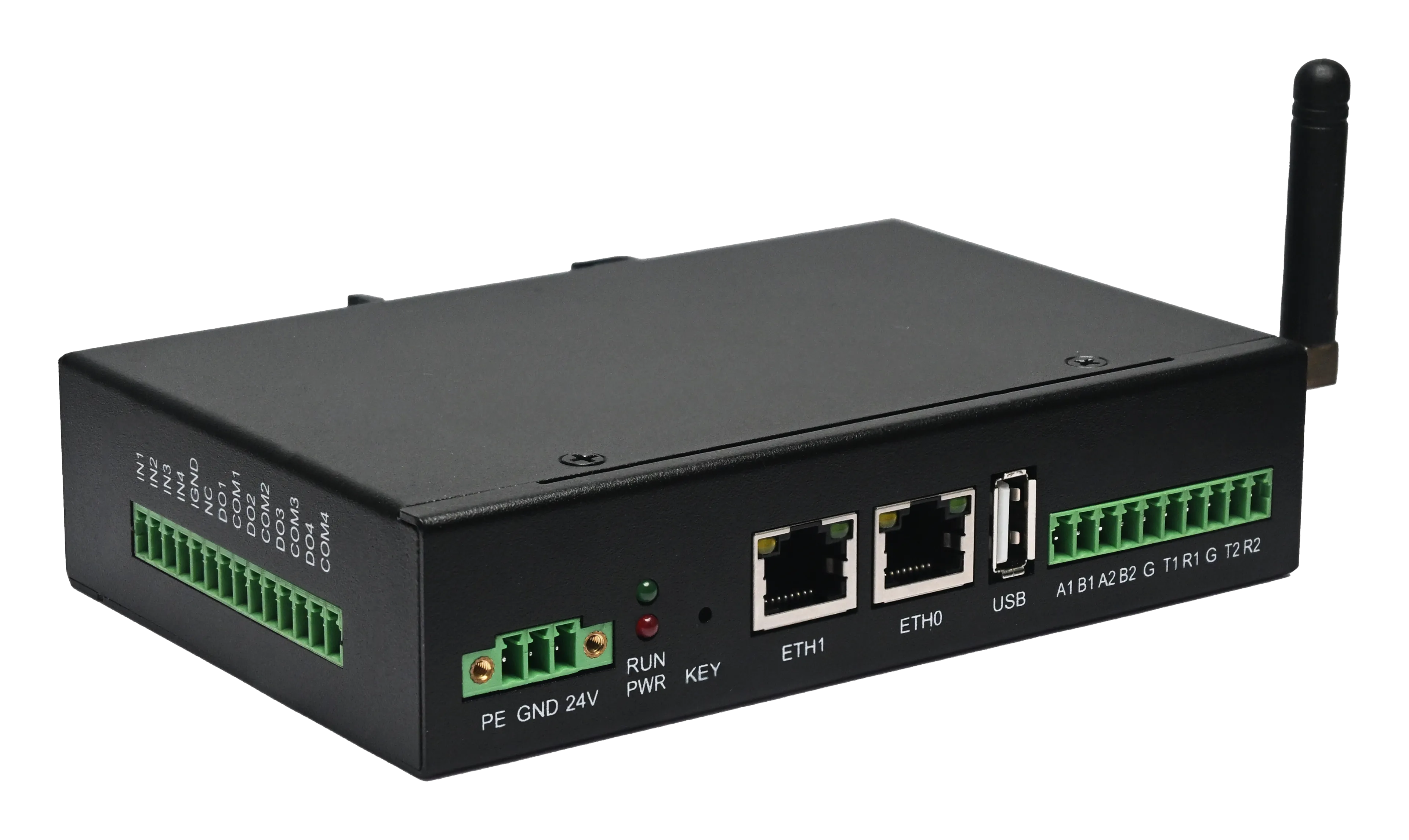
Power, network and field terminals, photographed on the unit itself.
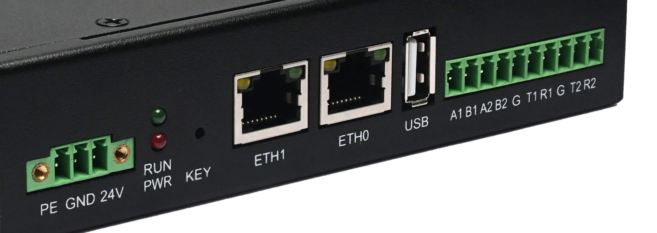
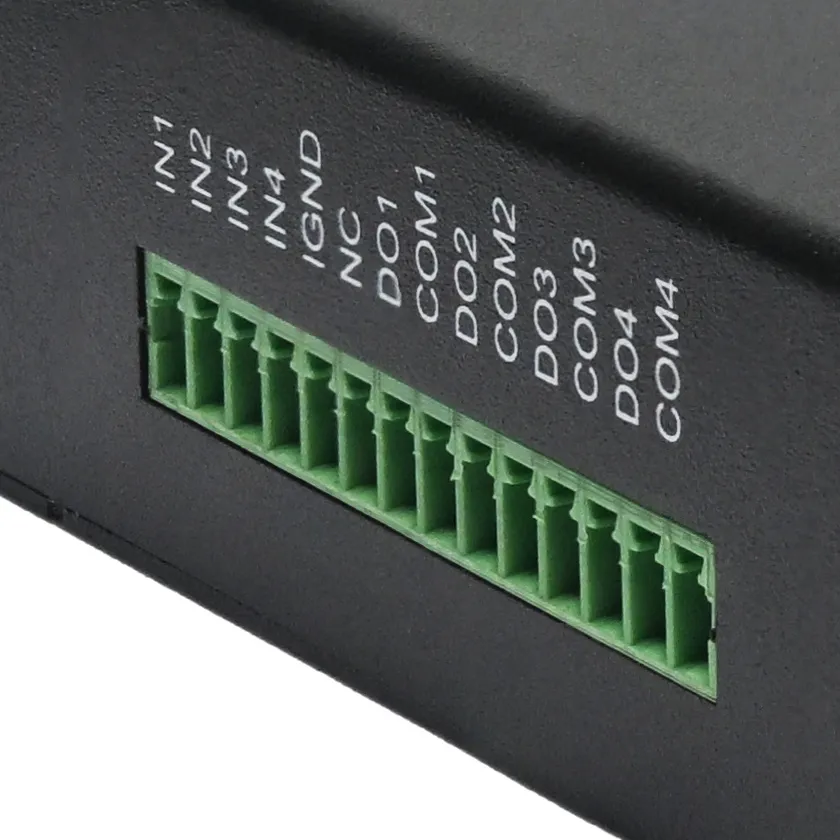
The unit photographed is the supplier factory baseline: the two ports labelled T1R1 and T2R2 are RS232, as the silkscreen shows. The DPE100 target configuration replaces those two RS232 ports with RS485; every other interface is unchanged. See the baseline column below for the full list.
Hardware specifications
Current hardware baseline
- 2 × RS485 + 2 × RS232
- 2 × RJ45 Ethernet ports
- WiFi (external antenna), optional 4G
- 1 × USB-A
- 4 × digital input / 4 × digital output
- 24 V DC power
Target specification
| Spec | DPE100 |
|---|---|
| RS-485 | 4 |
| Ethernet | 2 |
| Wi-Fi | 1 (Wi-Fi + BLE) |
| Cellular | 4G (optional) |
| Digital inputs | 4 |
| Digital outputs | 4 |
| Power | DC 12 / 24V |
| Operating temp. | −20 ℃ to +70 ℃ |
| Surge rating | EMC EFT/ESD level 3 + surge level 2 |
| Mounting | DIN rail + mounting ears |
| OS | Linux 6.1 |
| Human interface | Local web + cloud |
The local web page
Opened in a browser on site, and available through a network outage.
-
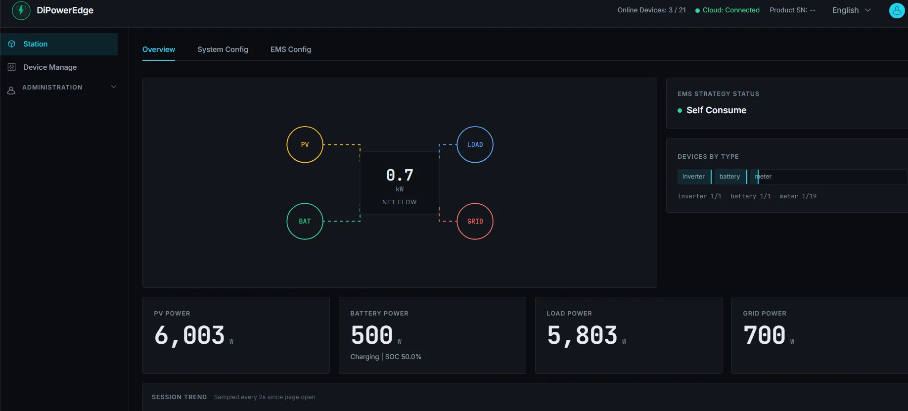
Live overview
Energy flow, four live power readings and strategy status.
-
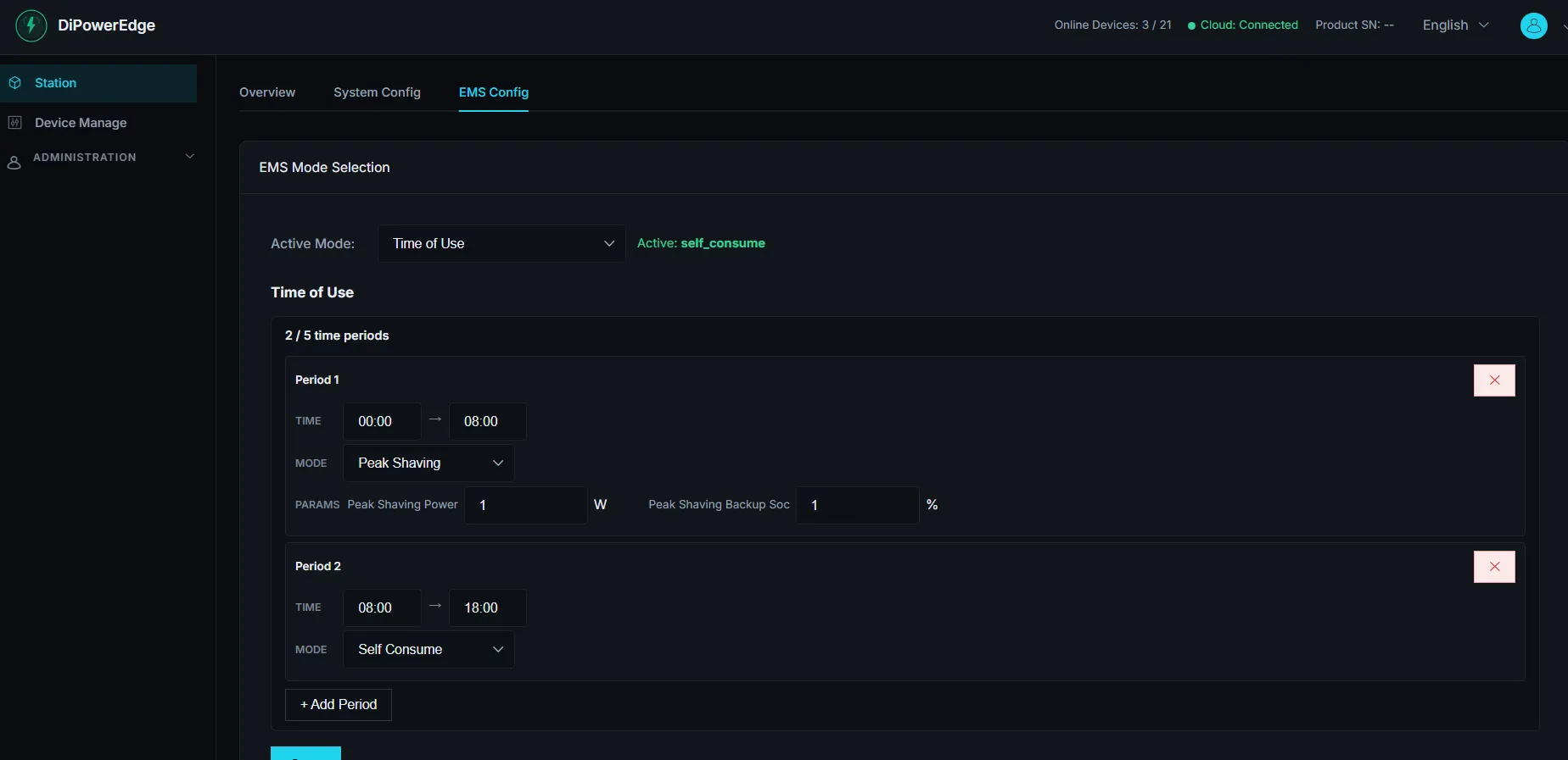
Policy configuration
Time-of-use windows and peak-shaving parameters are set locally.
Supported protocols
| Protocol | Transport | Note |
|---|---|---|
| Modbus | TCP/IP : 502 · RS-485 | Whether RTU is enabled on the RS-485 side is not yet hardware-confirmed, so Modbus RTU is not claimed as a confirmed capability. |
| SunSpec | over Modbus | — |
| MQTT | TCP/IP | — |
| IEC 60870-5-104 | TCP/IP : 2404 | — |
| IEC 61850 | MMS over TCP/IP | — |
Mounting
Supports 35 mm top-hat DIN rail (EN 50022) and screw-fixed ear mounting, in a metal enclosure suited to continuous operation inside a distribution cabinet.
Take one to your site
Tell us which devices you need to connect and what logic you need to run. We will assess it and come back with an integration plan.